The 200GMII / 400GMII Extenders
During the development of the underlying architecture, it was recognized that the system needed to be inherently flexible, as it would provide the foundation for future specifications. Developing solutions for any new specifications could require a different encoding, modulation, FEC, or some combination of the three that is different from what is specified in the 200GBASE-R or 400GBASE-R PCS.
While flexibility is desirable, it must be balanced with companies’ desires to leverage their existing investments in devices supporting 200GbE or 400GbE. So, to address these issues and create this inherent flexible architecture, the “MII Extender concept, first introduced as part of the 10 Gigabit Ethernet standard, was adopted. Figure 1 illustrates the 200GMII Extender and 400GMII Extender. These optional extenders consist of extender sublayers (“XS”) that convert the data stream to and from the MII interface with the respective physical AUI interface between them. 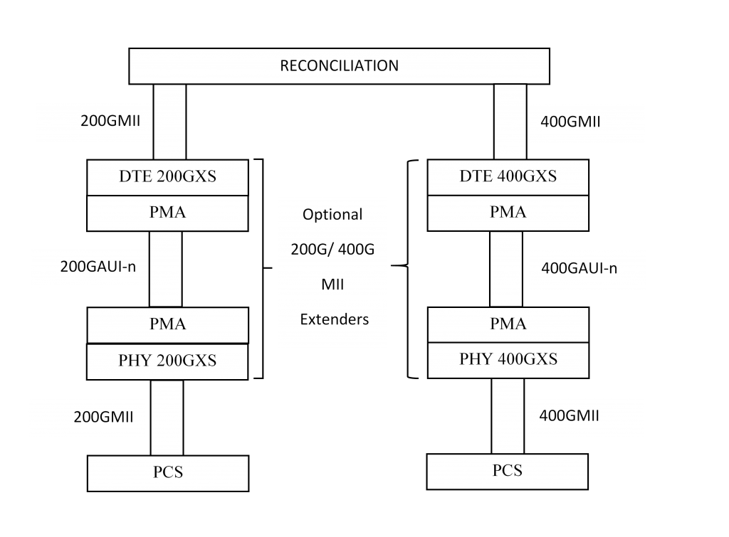
Figure 1 – 200GbE and 400GbE Extender Sublayers
The 200GXS and 400GXS support all the same functionality as the respective PCS’s, plus additional optional features related to FEC. This allows the system designer to configure a device either as a PCS or XS for the given rate. If configured as a PCS, then it would support the respective existing family of physical layer specifications.
Let’s consider the data flow when configured to support the respective extender. Starting at the transmit MII from the Reconciliation Layer, the DTE 200GXS or DTE 400GXS would handle all the same functions as the respective PCS. The data would then be carried by the AUI to the PHY 200GXS or PHY 400GXS, which would then convert the data stream back to the MII. This data is then encoded by the new PCS for the target physical layer specification. At the Rx side, the new PCS would decode the data back to the MII, which is then converted back to the standard encoding of the 200GBASE-R or 400GBASE-R PCS by the respective PHY XS. The data is then carried by the AUI back to the respective DTE XS, which performs the same functions as the respective 200GBASE-R or 400GBASE-R PCS.
With this approach, companies can invest in a device knowing an external PCS in either a discrete device or module could be used to support future physical layer specifications. It also provides a level of assurance for companies investing in switch products, knowing a standard Ethernet port can be populated with a module that includes the additional PCS to support a future physical layer specification.
Next time, we will take a more in-depth look at the respective 200GBASE-R or 400GBASE-R PCS’s.